Kiwi Roy made a great post on the V11 Lemans forum, and I thought I'd share my installation here. The ITI odometer stopped working, and the speedo wasn't the most accurate, so it was time to do something about it. Luckily Speedhut was running a 30% off sale last year, so I took advantage of it...
The V11 Sport takes the 3 3/8" gauges, and you can customize the faces of the gauges to your liking. I used the Eagle emblems that were supplied by another forum member, and choose dark blue for the back lighting. You'll have to modify the gauges to fit the back cover on, and you can opt for the GPS speedo, or go the mechanical sensor route. I chose the latter.
I stumbled upon a mechanical sensor (SEN-01 from Dakota Digital) that would fit onto the cable drive mount at the tranny, but would require some mods. The drive mount would have to be routed out a bit for the sensor to fit in so that it wouldn't interfere with the throttle linkage. A good friend took care of that for me in short order.
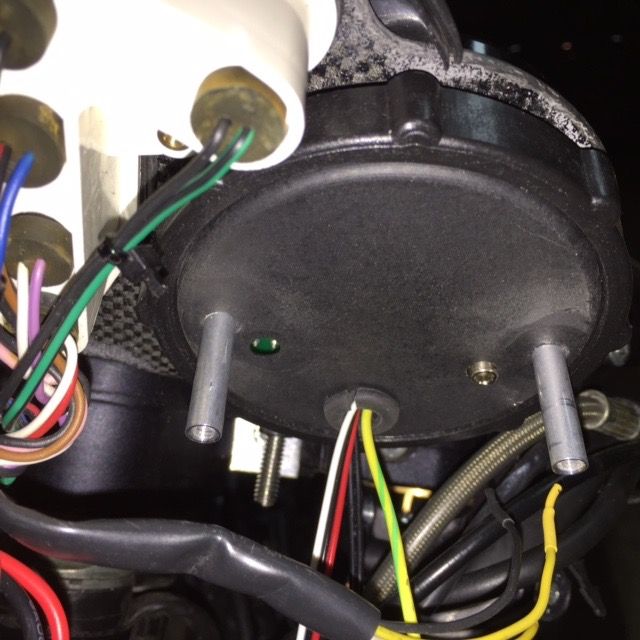
Next, I had to figure out a method to secure the back speedo cover onto the gauges. My first attempt was to apply JB weld to 4 tee nuts so I could use the existing mounting holes. Without much effort, the JB weld broke loose. I then had to take the gauges apart and I used 1" threaded couplers (8/32 thread) and secured them with machine screws from inside the gauges.
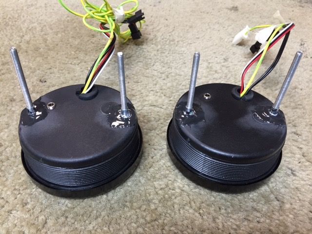
Wiring was fairly simple. You can tap into the existing harness (5A fuse recommended), but I already had a feed from the battery up front via a Fuzeblock. If you're getting both gauges, I would recommend getting the extra harnesses to couple them together, thus eliminating having to tie everything together separately. It will be more tidy that way.
Here's some pics for your enjoyment:
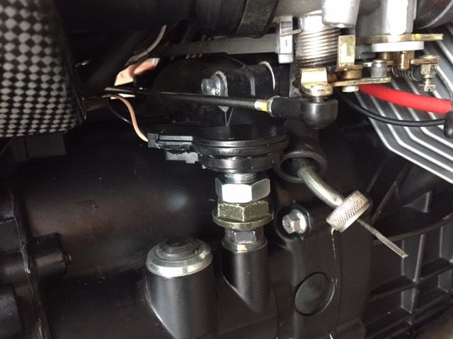
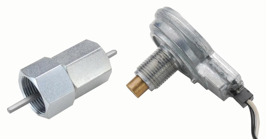
The Dakota Digital sender needs to fit inside the gear housing in order to clear the throttle linkage. There's an internal stop inside the housing for the gear drive, so you need to be careful how deep you route this out.
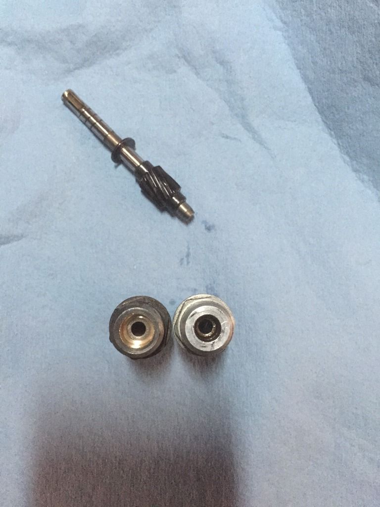
I made sure I had a spare housing (thanks Scud!) in case this experiment failed. The routed version is on the left hand side, an the original is on the right. The speedo gear is above both units.
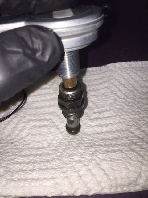
Here's the sending unit inside the housing as far as it will go. The sender is 5/8-18 thread, and the housing is m16-1.0 thread. Had to think about how to couple them together....
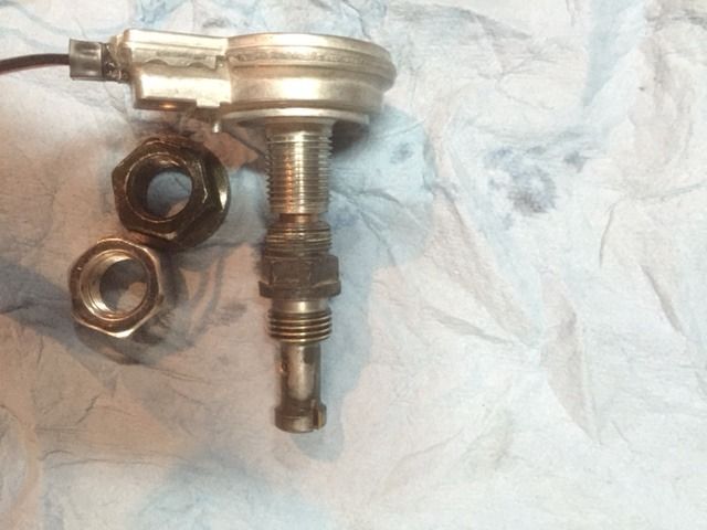
I have a metric bolt on the bottom, and an SAE bolt on top to act as a lock nut. Luckily, the two threads are fairly similar, and I can use the bottom metric nut to thread on 2 full turns onto the sending unit. The luck nut keeps it from coming loose. I might add a bit of loktite for good measure.
The sending unit uses a 1/8" "key" to operate, which is also the same size as the speedo cable. I did have to cut the key down to length in order to make it work. I wasn't able to use the mounting nuts that was supplied, as the sending unit would then be in the way of the throttle linkage.
A pic of the 1" threaded couplers to mount the back cover. Lining the up was a pain in the arse. I then used 1.5" machine screws to mount the cover.
Here's a pic of the tee nuts and JB weld that failed in no time. I even sanded and chemically cleaned the area first.
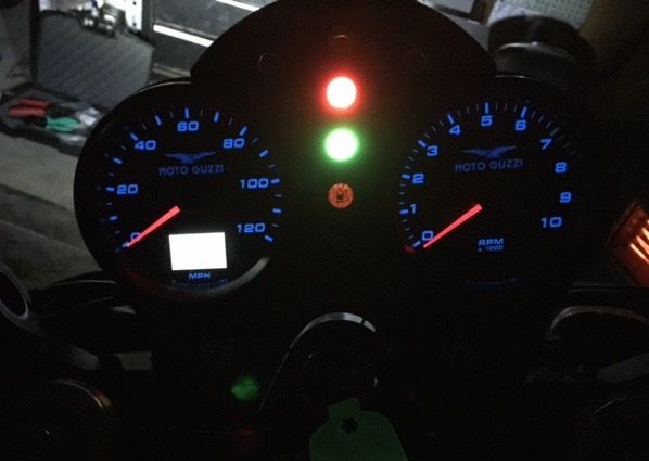
The gauges loosely in place. Take note of the yellow and red ticks on the tach that match the original ITI's.
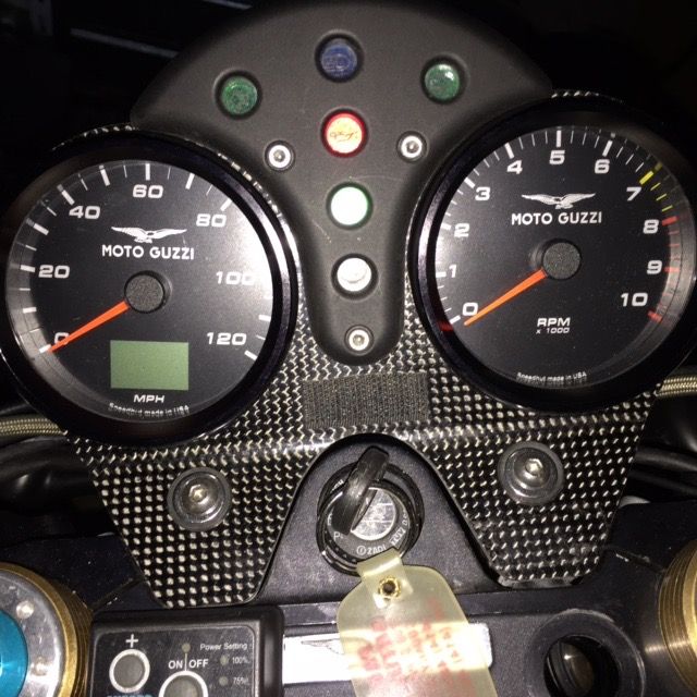
The gauges at night:
The how to by Kiwi Roy and others from the V11 Lemans forum:
http://www.v11lemans.com/forums/index.php?showtopic=19038&page=1I couldn't have done this without the help of the others from the above forum. Hopefully, this will help in the future.
Ken